Rotary capping layout
Eight capping heads are arranged around the rotary station.
Eight rotary heads
An automatic rotary capping machine with eight capping heads and a cap elevator, arranged inside an enclosed bottle-handling station.
01 / The machine
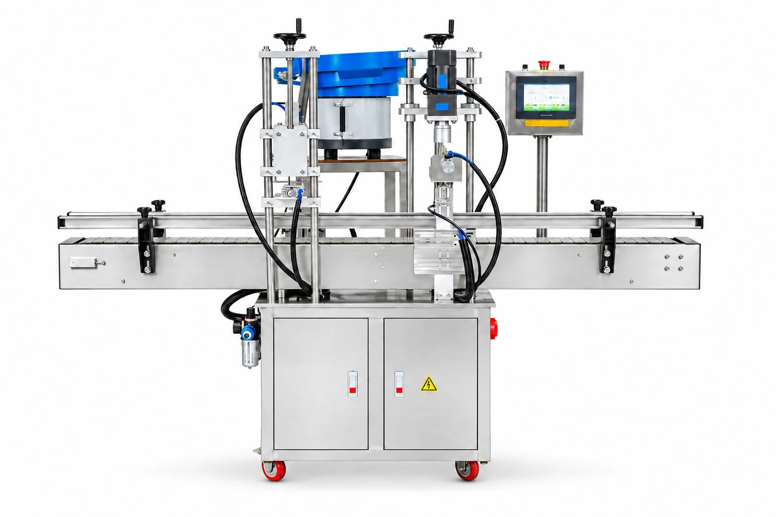
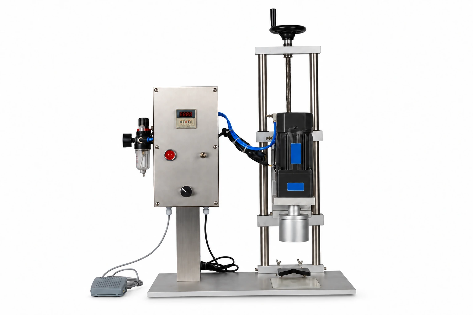
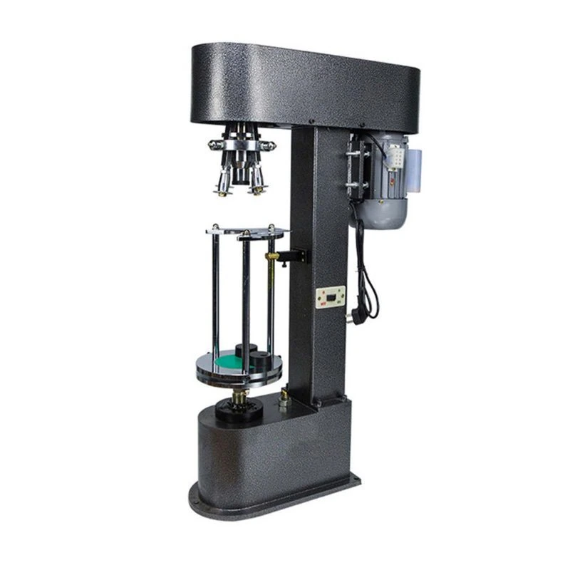
An eight-head rotary capping machine with screw-fed bottle spacing, automatic cap presentation and a guarded rotary working area. Bottles are transferred into the rotary station where the capping heads work around the carousel.
Eight capping heads are arranged around the rotary station.
An elevator supplies closures to the capping section.
The rotary mechanism sits within a guarded cabinet.
02 / In operation
From product preparation
to the next packaging step.
The infeed screw separates bottles for transfer to the rotary station.
The cap-feed arrangement supplies closures to the eight-head carousel.
Closed bottles transfer back to the outfeed conveyor.
03 / Technical details
Eight rotary heads
| Capping heads | 8 |
|---|---|
| Capping speed | 80–110 bottles/min |
| Cap diameter | 25–70 mm |
| Rated power | 2.5 kW |
| Power supply options | 220 / 380 V, 50/60 Hz |
| Approx. dimensions (L × W × H) | 4,000 × 900 × 1,925 mm |
| Approx. machine weight | 500 kg |
Output and tooling depend on the bottle and closure. Overall dimensions vary with the line arrangement.
04 / Your application
Start with your product and packaging. These details shape the equipment configuration.
Request a quoteSend bottle and cap samples; required closure tightness; bottle dimensions and output target. Photos or drawings help define the configuration.
The setup is matched to your product and packaging, required output, available space and local power supply. Include each pack size you plan to run.